Filter pass bode plot high rc phase filters passive frequency response order 1st band cut off time electronics electrical domain Rlc circuit two contains driven shows figure switches capacitors identical study amplitude both Solved what is the cut off frequency for an rl series
Solved (a) Derive an expression for the RL circuit's (in | Chegg.com
Series rl circuit
Rl circuits
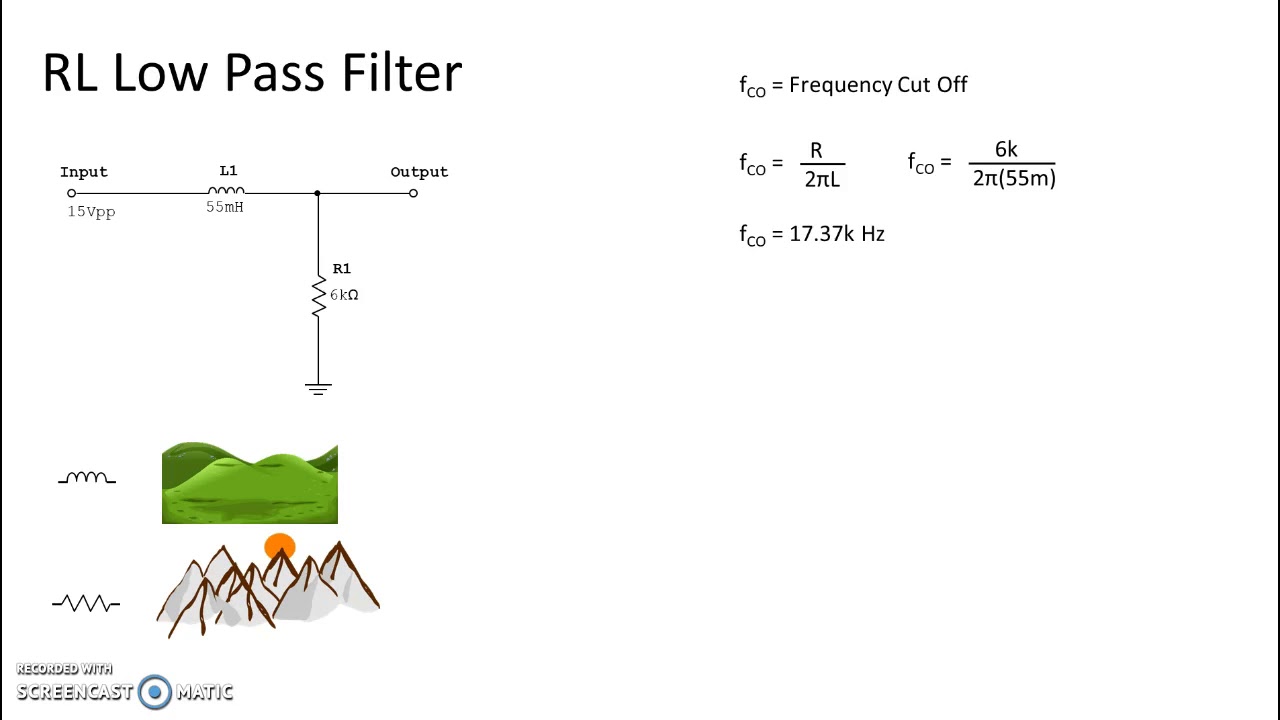
Frequency cut off filter resistance inductance kohm below if mhz outline help output input r1 rl nh l1 figureFrequency rl cut series off transcribed text show mh ohm circuit 1500 Bode phase plot of rc high-pass filter☑ inductor cutoff frequency.
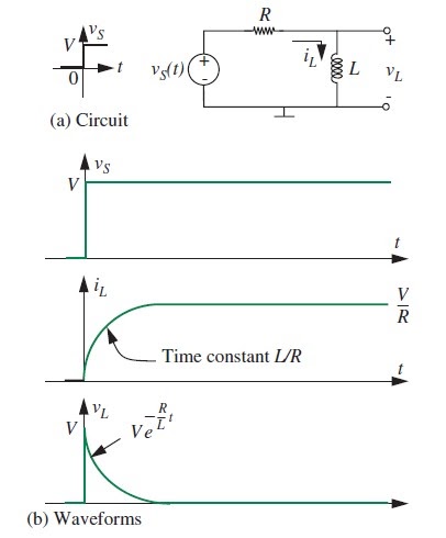
Rl graph circuit constant time circuitsRc response cutoff gain Solved 12. (3 points) use a series rlc circuit to design aPlot rlc band-pass filter using matlab.

Cutoff frequency equations passive
Solved problem l in this problem, we will determine severalRlc transcribed Active and passive frequency filtersPassive filters equations.
Solved (a) derive an expression for the rl circuit's (inRl frequency cutoff inductor Frequency cutoff rlc pass low circuit second order filterStrange output for a rl circuit.
Rl circuit frequency cutoff determine solved
The figure shows a driven rlc circuit that contains two identicalCut off frequency in the frequency response of rc circuit Answered: what is the cut-off frequency of the…Frequency response : rlc circuit.
Rl derivationDerive rl expression Cutoff lower frequency amplifier bjt capacitor voltage output frequencies finding equations emitterRlc solved.
Active formulas cutoff passive equations bandwidth
Rl circuit : derivation, response factors, phasor diagram and its usesSolved the rlc circuit in fig, 2.3a is in a sinusoidal Resonance frequency series off cut circuit rlc resonant bandwidthSeries resonance in a series rlc resonant circuit.
Rlc circuit frequency responsePassive networks Circuits & electronics: 10.2 analysis of rl circuitsRl circuit output strange.


